
PRODUCTS
MESSAGES
Acousto-Optic Deflectors
Keyword:
Acousto-Optic Deflectors
Category:
- Description
- Parameters
- CAS'TechClass
-
Devices designed specifically for high-speed solid-state scanning of light beams
Acousto-optic deflectors (AODF) can achieve laser beam scanning by changing the RF driving frequency, and the scanning position can achieve random position, continuous line scanning, and sequential point deflection. Depending on crystal, wavelength, and beam size, scan rates in excess of 200 MHz can be achieved, along with precise position control of nRad.
The optimal efficiency of an AOD typically requires the input laser beam to be set at a Bragg angle, when scanning the laser beam a Bragg angle mismatch occurs, this is due to the fact that the AOD can only be optically aligned at one drive frequency. This generally results in lower efficiency. CASTECH's team has the design experience to cleverly solve the problem, such as using longitudinal modes and using phased array piezoelectric cells within the transducer to design and produce large bandwidth AODs with high resolution.
CASTECH design AOD for 1D and 2D scanning, and together with the specially developed broadband RF driver, we can realize various control methods such as frequency sweeping and chirping, which makes it easy for customers to realize multiple functions quickly.Applications:
●Laser direct writing
●Wafer inspection
●Precision circuit board drilling
●Biological cell detection
●Optical tweezers
CASTECH's products are produced independently throughout the entire process and can be customized according to customer needs. Refer to the following list for standard products.
Key words:- low insertion loss
-
Model Number:
1D-Deflectors CADF-f-r-a-mt-w-cn-h
2D-Deflectors CADFD-f-r-a-mt-w-cn-h
Center Frequency(f)
RF Range(r)
Aperture
(a)
Material
(m)
Mode
(t)
Wavelength (w)
RFConnector
(c)
Number of connectors
(n) *
Housing
(h)
070 (70MHz)
…
10 (±10 MHz)
…
010
(1 mm)
…
CQ (Crystalline Quartz)
TE (TeO2)
C (Compressional)
S (Shear)
266 (266nm)
…
AF (SMA-F)
…
D(Double-Input)
A33
…
* Only applicable to dual RF type acoustooptic deflectors
Typical Specifications
Wavelength
Aperture
Operation frequency
Scan dimensions
Scanning Angle
Diffraction Efficiency
Material
266 nm
1×30 mm2
210±60 MHz
1D
5.5 mrad
>60 %
CQ
355 nm
≥7 mm
160±40 MHz
1D
4.9 mrad
>85 %
CQ
364 nm
8 mm
100±25 MHz
1D
35.5 mrad
>70 %
TE
405 nm
8 mm
120±25 MHz
1D
32.0 mrad
>70 %
TE
488 nm
2 mm
180±40 MHz
1D
60.5 mrad
>65 %
TE
532 nm
≥7 mm
140±30 MHz
1D
5.5 mrad
>85 %
CQ
532-633 nm
8-10 mm
100±25 MHz
1D
43.0 mrad @592 nm
>70 %
TE
780-905 nm
8 mm
100±21 MHz
1D
53.0 mrad @820 nm
>70 %
TE 1064 nm
6 mm
80±15 MHz
1D
5.5 mrad
>80 %
CQ
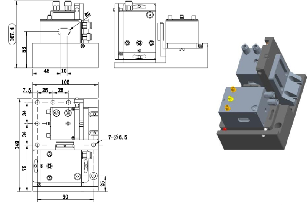
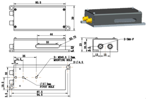
1064 nm 1-7 mm 90±16 MHz 1D 50 mrad >80 % TE 355 nm 7 mm 160±40 MHz 2D 4.9×4.9 mrad >60 % CQ 532 nm 10 mm 85±25 MHz 2D 40×40 mrad >40 % TE Housing dimensions(mm):
F23
C66
Previous page
Next
Previous
Next
Inquiry List